Disclaimer: This post is for reference only. Electrical skills are required to read and understand this post. Please first read the post and decide whether to follow this. Make sure you are electrically competent to follow this post.
This is another frequently asked questions " How do I wire my Keenovo heater pad to my 3D printer via an SSR?" and in some cases, we were astonished to find customers following wrong guides on this task. Thus, we feel the necessity to compose this post.
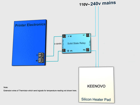
Here is how the wiring should be done correctly as shown in the diagram below: (Please check this if the picture is not clear.)

Important Notes:
- Check if your Keenovo heater pad rating is compatible with your mains. If you are using a 110V/120V Keenovo heater pad, please connect it to 110V/120V. If it's 220V/230V/240V, please plug it to 220V ~240V. 110V pads work well at 120V, same as 220V pads at 240V. However, never use 110V/120V pads at 240V. No polarity between the two power wires( commonly in silicone and white fiberglass sleeve insulation).
- Thermistor extension wires ( commonly 22AWG in red) are not shown in the above diagram. Please simply connect the extension wires to the correct terminals on the mainboard for accepting temperature signal from the heater pad. (Corresponding terminals to read temperatures from the thermistor sensor.) Also, no polarity between the two sensor wires.
- The SSR should be DA by type meaning DC input to control AC output. (There is also DD or AA SSR which will not work in this task). If possible, please choose an SSR with big copacity like this one: C-Lin SSR.
- Polarity MATTERS at the DC input side of the SSR as well as with the terminals for sending signals from the mainboard to control the SSR. You may need to find some extra wires for this purpose, technically any common wire gauge shall work.
- It may help to understand the working of the wiring by considering the output side of the SSR as an on/off switch and the input side of the SSR as the trigger for it to be on or off.
- Last but not least, proper grounding of the aluminum plate with which the heater pad is in direct contact is strongly suggested.

Hi David Cushman, Please kindly contact us via email for the CR10 S5 drawing. It’s always recommended to apply a thermal fuse or a built-in thermostat for overheating protection. We can add it upon request, and some of our standard pads are built with thermostats. The main purpose of this drawing here is to show the SSR wiring, so thermostat/fuse is not indicated. Thank you!
Hi Gary G, Yes, with an SSR, PID tuning is possible.
Hi Gary G, With an SSR, PID tuning is possible.
Hi – I’ve seen folks put videos of this up, and the diagram above. Would we be able to (or required) to enable bed pid tuning once the SSR is in place? I’m not sure if this is basically the marlin bang-bang method, and if PID tuning requires a mosfet versus an SSR – thank you very much!
Is it possible to get a diagram of the hole locations of the cr10 s5 24 hole 120vac heater? I am doing a scratch build (increasing the build size of a ender 5 plus) and figured using the stock parts for the 510mm x 510mm bed may save me a little bit.
Also, in your hookup wiring diagram, why is there no thermal fuse in the 120 VAC line for run away situations? Is it just the difficulty of safely wiring it in? I would think this would be a mandatory add on for the mains heaters. Comments please?